The Wet Cell Hydrogen Generator
Hydrogen Generator

Process of Design
From the beginning
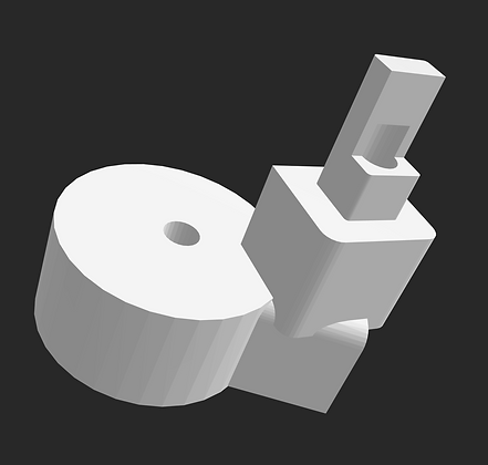
The first electrode cap designed to hold an aluminum electrode (the longer slit in the cap), an electrode opening (the small hole in the cap) and a gas flow port (the threaded section in the cap '1/2in diameter).

Producing an Gas Tight Electrode Holding Cap Part 1
After testing the last gas cap, test results showed poor holding of the generated hydrogen gas resulting in loss of product. To fix these issues I modified the cap so that there would be a protruding base allowing for the cap to be inserted tightly into the acrylic tube creating a seal to prevent gas from leaking out. An added wire inlet was also added located at the reversed "L" shaped carving on the top of the cap to allow for better wire management. An added slit was added in the center of the interior of the gas cap to allow an aluminum electrode plate to be inserted and held in place during electrolysis.

Producing a Gas Tight Electrode Holding Cap Part 2
Testing part 1 of a gas tight electrode holding cap resulting in leaks around the cap's inserted base in the acrylic tubing. To fix this I added a ring carving into the wall of the base that was inserted into the acrylic tube allowing a custom made silicone o-ring to be placed there to form a seal preventing gas from escaping.

Examples of the custom made silicone o-rings


Adding Grphite Electrode Slots for The Electrode Cap
After many test runs using aluminum and stainless-steel electrodes. Corrosion and various different forms of metal oxides became a problem as foam was generated over usage time. This caused increased inefficiencies, trapping hydrogen and oxygen gas in the form of bubbles and potentially generating hazards in the form of hexavalent chromium oxides. With these problems in mind, I selected graphite rods to be my new electrodes having a lower corrosion rate along with being readily available and cheap.
Electrically connecting all five electrodes was an enduring task. I had to find a way to connect the electrodes to wires while also making sure that I kept a gas tight seal so no gases would escape. My design idea was to have five 14-gauge solid copper wires be inserted into the electrodes cap by using AutoCAD to create wire holes for each electrode holder. To make sure that no gas would escape after inserting the copper wires, I used silicone calking to seal any gaps around the inserted wires in the top of the gas cap.
A second 1/2 in diameter threaded hole was designed into the cap. This extra threading served for a water circulating inlet. Silicone piping was used to allow water from the bottom of the electrolysis device to be pumped to the gas cap creating water circulation throughout the system. The water circulation served to eliminate foam from being generated as the electrolysis reaction took place.
Lastly tabs were added to the gas cap acting as handles for the cap. From the previous version without handles, the tight seal of the custom silicone o-rings cased large amounts of difficulty when removal of the cap was need for cleaning, data gathering, and replacement of electrodes.
Note: I would later learn that these electrodes have corrosion issues due to oxidation and physical decompositions exponentially increasing over usage time.

Grphite Electrode Slots


Addition of Water Jet Nozzles to Gas Cap
Analyzing stress test results on the electrolysis system showed that over time heat generated by electrolysis inefficiencies raised temperatures to the melting point of the PLA material the gas cap was constructed from. To prevent the whole system form literally melting down after prolonged use, I added water jet streams to spray onto the graphite electrodes. This cooled the area of the electrodes that were inserted into the gas caps electrode holding area.

Water Jet Nozzle
Creating an Array of Water Jets
The next step in the design plan was to make sure all five electrodes were getting saturated with the circulated water. From design analysis of the previous cap with only 2 water jet nozzles the five graphite electrodes were being adequately lubricated with water mostly in areas that were closer to where the two nozzles were placed. To improve this, I decided to put five nozzles in a circle around the inside of the cap aimed to hit each electrode individually. This provided a direct point of contact for the water to be sprayed onto allowing all five electrodes to be fully saturated when water was being pumped through the system.

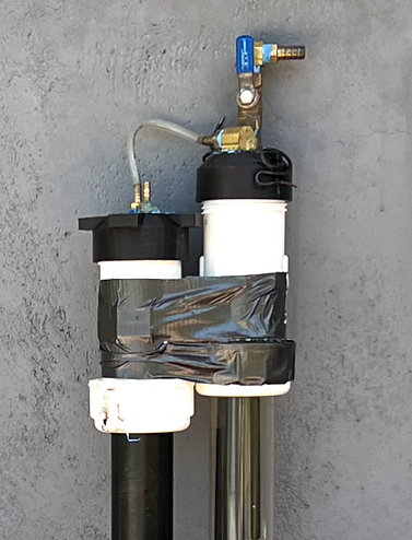
Electrode Cap With Twist Removal Design
After winning 3rd place in the innovation design track category, I decided to continue my pursuit in designing an electrode cap. The goals for this new electrode cap were to alleviate the need for a custom silicone o-ring gasket along with improving how the cap was placed and removed from the acrylic tube when maintenance was required.
The design process included me analyzing current parts that I had already bought for the electrolysis machine during my construction of it for the innovation pitch competition. I realized that instead of buying a new 2in diameter screw adapter to connect a new cap to the acrylic tube. I could use one of the compression couplers that I had been using to connect the acrylic tubing to a PVC pipe that was connect to a P-Trap union with a clear out drain.
I designed an electrode cap that could screw onto one side of the compression coupler. This allowed for easy installation and removal without the need for pressing or pulling on the cap along with no need for a custom silicone o-ring gasket.

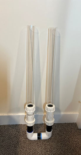
Compression Coupler
P-Trap Union with Clear Drain
2in Diametor Acrylic Tubing
Screw On Electrode Cap
Screw On Gas Cap
Compression Couplers
State of The Art Coupling Tape
Water Inlet
Gas Pressure Equalizer

Final Design of The Electrode Gas Cap
After test analysis of the last electrode cap with twist removal design I found a few flaws that could be further improved. I noticed that having narrower output holes for the water nozzles created extra bubbles from increased exit pressure the water experienced when leaving the nozzles. To counter act this, I designed larger nozzle hole diameters to lower the output pressure. I then noticed that the bubbles being formed off of the electrodes from the electrolysis reaction would sometimes get stuck on the electrodes causing gaps reducing production. Fixing this required some serious thinking. After watching a video of someone creating a water vortex for solving a problem involving soap bubbles forming within a solution. I got the idea that I could apply the same principle from the video that I watch to the bubbles created from electrolysis reaction in my machine. The goal was to guild the gas bubbles to the center of the acrylic tube using a water vortex, allowing them to merge together and more easily float to the top and out of the reaction chamber. To create the vortex, I decided to add a second water entry point with a guiding tube that was placed at an angle. When water came out of this angled exit port it would push water in the tube in a clockwise direction starting and keeping a water vortex cycle in motion.
Other improvements included increased submersion of electrodes, 2 additional points of contact to help in the removal of the cap for maintenance, improved electrical connection to electrodes, and semicircle water flow design to remove complex water channels within the cap.
The goals for the improved electrical connections to the electrodes in the cap were to eliminate the need for using silicone sealant, and to improve the gas leakage from the wire entry points into the cap. To do this I decided to use M2 screws and a small section of 14-gauge wire at the contact points within the electrode holding unit. The process involved me inserting about 12mm of wire until it completely filled the electrode holding component guaranteeing contact. Next, I then screwed the M2 screw until it made good electrical contact with the already inserted copper wire. To seal any possible gas leaks from the M2 screws I used liquid rubber around the areas where the screws were put into place stopping any gas from escaping.
Improving the amount of submerged depth the electrodes had when the cap was screwed into place involved lowering (depending on your perspective) the electrode housing unit in the cap.

Design of The Graphite Electrode Cap for Presentation to Invention Pitch Competition
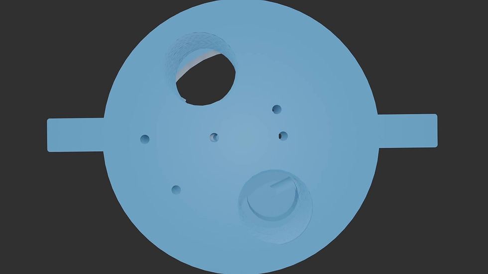
Electrode Gas Cap Description
The electrode cap was designed to hold five 3/8th inch diameter graphite rods, one as the anode and four as cathodes. Through multiple tests I quickly learned that the heat generated from the reactions would heat the graphite rods to a point where the PLA material that the cap was 3D printed from would melt and the electrodes would fall out. To counteract these high temperatures. I designed internal cavities to have water cool the PLA material along with spraying water onto the electrodes causing them to be cooled. As an added benefit from the water being circulated through the system it allowed heat that would build up near the electrodes from electrolysis inefficiencies to be lessened due to a fresh supply of cool water coming from the cap up top. The video animation shows the cavities and electrode holdings designed into the cap.
Note: My theory was having more surface area for the cathode would allow for more hydrogen production. I later learned that the splitting of H2O does not care about electrode area ratios but rather in terms of total electrode surface area.

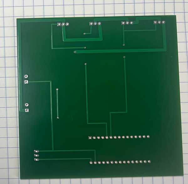
PCB Board For Inverter Circuit Design
The goal of the inverter circuit was to have the elctrodes alternate between being the cathode and anode for material testing purposes.
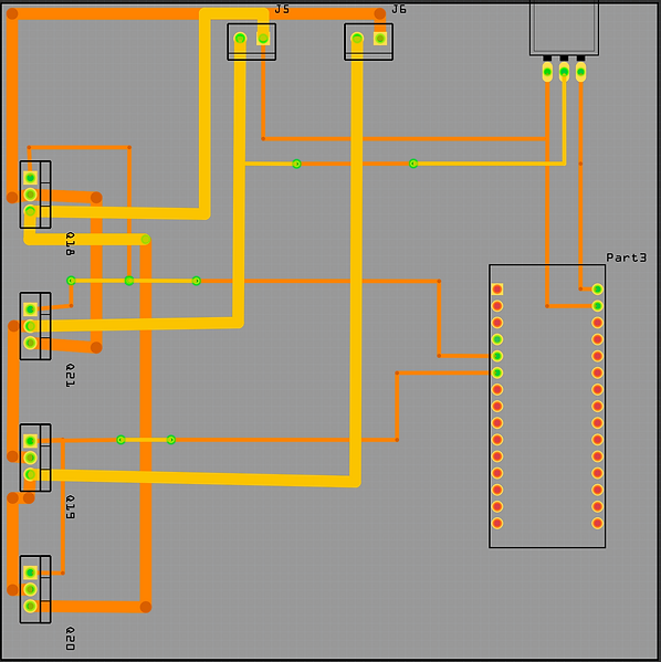
Actual PCB board Front and Back
Front Side

Back Side